CONTACT INFO

Lightning arrester
- Commodity name: Lightning arrester
Category
Contact Info
Product Details
Overview
Surge arresters are the foundation of the insulation coordination of various electrical equipment in power systems (transformers, reactors, capacitors, generators, motors, PTs, CTs, circuit breakers, contactors, and all other medium and high-voltage electrical equipment). The protection performance of surge arresters determines the internal and external insulation indicators (short-term power frequency withstand voltage, lightning impulse withstand voltage, and operation impulse withstand voltage, etc.) of all electrical equipment in the power system. Metal Oxide surge Arrester (hereinafter referred to as MOA) is an advanced product among conventional surge arresters. The core working element uses a多元金属氧化物粉末 (multicomponent metal oxide powder) mainly composed of zinc oxide, which has excellent non-linear voltage-current characteristics, fast steep wave response, and large current carrying capacity.
Model Description

Technical Parameters
Table 1 Electrical Characteristics of Conventional Surge Arresters 10kV and Below
| Application Scenarios | System Nominal Voltage (kV) | Arrester Model | Arrester Rated Voltage (kV) | Arrester Continuous Operating Voltage (kV) | DC 1mA Reference Voltage (kV) ≥ | Leakage Current at 0.75DC Reference Voltage (μA) ≤ | 8/20 Lightning Impulse Residual Voltage (kV) ≤ | 30/60 Operation Impulse Residual Voltage (kV) ≤ | 1/4 Steep Wave Impulse Residual Voltage (kV) ≤ | 2000μs Square Wave Current Carrying Capacity (A) |
| Low Voltage | 0.22 | Y(H)1.5W-0.28/1.3 | 0.28 | 0.24 | 0.6 | 50 | 1.3 | - | - | 75 |
| 0.38 | Y(H)1.5W-0.5/2.6 | 0.5 | 0.42 | 1.5 | 50 | 2.6 | - | - | 75 | |
| Power Distribution | 3 | Y(H)5WS-5(3.8)/15 | 5(3.8) | 4.0(2.0) | 7.5 | 50 | 15.0 | 12.8 | 17.3 | 75 |
| 6 | Y(H)5WS-10(7.6)/30 | 10(7.6) | 8.0(4.0) | 15.0 | 50 | 30.0 | 25.6 | 34.6 | 75 | |
| 10 | Y(H)5WS-17(12.7)/50 | 17(12.7) | 13.6(6.6) | 25.0 | 50 | 50.0 | 42.5 | 57.5 | 75 | |
| Power Station | 3 | Y(H)5WZ-5(3.8)/13.5 | 5(3.8) | 4.0(2.0) | 7.2 | 50 | 13.5 | 11.5 | 15.5 | 200 |
| 6 | Y(H)5WZ-10(7.6)/27 | 10(7.6) | 8.0(4.0) | 14.4 | 50 | 27.0 | 23.0 | 31.0 | 200 | |
| 10 | Y(H)5WZ-17(12.7)/45 | 17(12.7) | 13.6(6.6) | 24.0 | 50 | 45.0 | 38.0 | 51.8 | 200 | |
| Capacitor | 3.15 | Y(H)5WR-5(3.8)/13.5 | 5(3.8) | 4.0(2.0) | 7.2 | 50 | 13.5 | 10.5 | - | 400 |
| 6.3 | Y(H)5WR-10(7.6)/27 | 10(7.6) | 8.0(4.0) | 14.4 | 50 | 27.0 | 21.0 | - | 400 | |
| 10.5 | Y(H)5WR-17(12.7)/46 | 17(12.7) | 13.6(6.6) | 24.0 | 50 | 46.0 | 35.0 | - | 400 | |
| Motor | 3.15 | Y(H)2.5WD-4(3.8)/9.5 | 4(3.8) | 3.15(2.0) | 5.7 | 50 | 9.5 | 7.6 | 10.7 | 400 |
| 6.3 | Y(H)2.5WD-8(7.6)/18.7 | 8(7.6) | 6.3(4.0) | 11.2 | 50 | 18.7 | 15.0 | 21.0 | 200 | |
| 10.5 | Y(H)2.5WD-13.5(12.7)/31 | 13.5(12.7) | 10.5(6.6) | 18.6 | 50 | 31.0 | 25.0 | 34.7 | 200 | |
| Generator | 3.15 | Y(H)5WD-4(3.8)/9.5 | 4(3.8) | 3.15(2.0) | 5.7 | 50 | 9.5 | 7.6 | 10.7 | 400 |
| 6.3 | Y(H)5WD-8(7.6)/18.7 | 8(7.6) | 6.3(4.0) | 11.2 | 50 | 18.7 | 15.0 | 21.0 | 400 | |
| 10.5 | Y(H)5WD-13.5(12.7)/31 | 13.5(12.7) | 10.5(6.6) | 18.6 | 50 | 31.0 | 25.0 | 34.7 | 400 | |
| 13.8 | Y(H)5WD-17.5/40 | 17.5 | 13.8 | 24.4 | 50 | 40.0 | 32.0 | 44.8 | 400 | |
| 15.75 | Y(H)5WD-20/45 | 20 | 15.75 | 28 | 50 | 45.0 | 36.0 | 50.4 | 400 | |
| 18.0 | Y(H)5WD-23/51 | 23.0 | 18.0 | 31.9 | 50 | 51.0 | 40.8 | 57.0 | 400 | |
| 20.0 | Y(H)5WD-25/56.2 | 25.0 | 20.0 | 25.4 | 50 | 56.2 | 45.0 | 62.9 | 400 |
Table 2 Electrical Characteristics of Conventional Surge Arresters 35kV and Above
| System Nominal Voltage (kV) | Application Scenarios | Arrester Model | Arrester Rated Voltage (kV) | Arrester Continuous Operating Voltage (kV) | DC 1mA Reference Voltage (kV) ≥ | Leakage Current at 0.75DC Reference Voltage (μA) ≤ | 8/20μs Impulse Current Residual Voltage (kV, Peak) ≤ | 30/60μs Operation Impulse Current Residual Voltage (kV, Peak) ≤ | 1/4 Steep Wave Impulse Current Residual Voltage (kV, Peak) ≤ | 2000μs Square Wave Current Carrying Capacity (A) |
| 35 | Power Station | Y(H)5WZ-51(42)/134 | 51(42) | 40.8(23.4) | 73 | 50 | 134 | 114 | 154 | 400 |
| Capacitor | Y(H)5WR-51(42)/134 | 51(42) | 40.8(23.4) | 73 | 50 | 134 | 105 | - | 400 | |
| Line | Y(H)5WX-51(42)/134 | 51(42) | 40.8(23.4) | 73 | 50 | 134 | 114 | 154 | 400 | |
| YHSWX-54/150 | 54(42) | 40.8 | 77 | 50 | 150 | 128 | 169 | 400 | ||
| Line Suspension Type | HY5CX-42/120 | 42 | 70.0 | 240 | - | 120 | - | 138 | 400 | |
| 66 | Power Station | Y(H)5WZ-84/221 | 84 | 67.2 | 121 | 50 | 221 | 188 | 254 | 600 |
| Y(H)5WZ-90/235 | 90 | 72.5 | 130 | 50 | 235 | 201 | 270 | 600 | ||
| Y(H)10WZ-84/221 | 84 | 67.2 | 121 | 50 | 221 | 188 | 248 | 600 | ||
| Y(H)10WZ-90/235 | 90 | 72.5 | 130 | 50 | 235 | 201 | 264 | 600 | ||
| Line | YHSWX-96/250 | 96 | 75 | 140 | 50 | 250 | 213 | 288 | 600 | |
| YHSWX-96/275 | 96 | 75 | 154 | 50 | 275 | 234 | 316 | 600 | ||
| 110 | Power Station | Y(H)5WZ-100/260 | 100 | 78 | 145 | 50 | 260 | 221 | 399 | 600 |
| Y(H)5WZ-102/266 | 102 | 79.6 | 148 | 50 | 266 | 226 | 305 | 600 | ||
| Y(H)5WZ-108/281 | 108 | 84 | 157 | 50 | 281 | 239 | 323 | 600 | ||
| Y(H)10WZ-100/260 | 100 | 78 | 145 | 50 | 260 | 221 | 291 | 600 | ||
| Y(H)10WZ-102/266 | 102 | 79.6 | 148 | 50 | 266 | 226 | 297 | 600 | ||
| Y(H)10WZ-108/281 | 108 | 84 | 157 | 50 | 281 | 239 | 315 | 600 | ||
| Line | YHSWX-108/281 | 108 | 84 | 157 | 50 | 281 | 239 | 323 | 600 | |
| YHSWX-108/309 | 108 | 84 | 173 | 50 | 309 | 263 | 348 | 600 | ||
| YH10WX-108/281 | 108 | 84 | 157 | 50 | 281 | 239 | 315 | 600 | ||
| YH10WX-108/309 | 108 | 84 | 173 | 50 | 309 | 263 | 348 | 600 | ||
| 220 | Power Station | Y(H)10WZ-192/500 | 192 | 150 | 280 | 50 | 500 | 426 | 560 | 600 |
Table 3 Electrical Characteristics Table of Conventional Neutral Point Arrester
| Application Scenarios | System Nominal Voltage (kV) | Arrester Model | Arrester Rated Voltage (kV) | Arrester Continuous Operating Voltage (kV) | DC 1mA Reference Voltage (kV) ≥ | Leakage Current at 0.75DC Reference Voltage (μA) ≤ | 8/20μs Lightning Impulse Current Residual Voltage (kV, Peak) ≤ | 30/60μs Operation Impulse Current Residual Voltage (kV, Peak) ≤ | 2000μs Square Wave Current Carrying Capacity (A) |
| Motor | 3.15 | Y(H)1.5W-2.4/6 | 2.4 | 1.9 | 3.4 | 50 | 6.0 | 5.0 | 400 |
| 6.3 | Y(H)1.5W-4.5/12 | 4.8 | 3.8 | 6.8 | 50 | 12.0 | 10.0 | 400 | |
| 10.5 | Y(H)1.5W-8/19 | 8.0 | 6.4 | 11.4 | 50 | 19.0 | 15.9 | 400 | |
| 13.8 | Y(H)1.5W-10.5/23 | 10.5 | 8.4 | 14.9 | 50 | 23.0 | 19.2 | 400 | |
| 15.75 | Y(H)1.5W-12/26 | 12 | 9.6 | 17.0 | 50 | 26.0 | 21.6 | 400 | |
| 18.0 | Y(H)1.5W-13.7/29.2 | 13.7 | 11.0 | 19.5 | 50 | 29.2 | 24.3 | 400 | |
| 20.0 | Y(H)1.5W-15.2/31.7 | 15.2 | 12.2 | 21.6 | 50 | 21.7 | 26.4 | 400 | |
| Transformer | 35 | Y(H)1.5W-30/80 | 30 | 24 | 44 | 50 | 80 | 67.5 | 400 |
| 110 | Y(H)1.5W-60/144 | 60 | 48 | 85 | 50 | 144 | 135 | 400 | |
| 110 | Y(H)1.5W-72/186 | 72 | 58 | 103 | 50 | 186 | 174 | 400 | |
| 220 | Y(H)1.5W-144/320 | 144 | 116 | 205 | 50 | 320 | 299 | 400 | |
| 330 | Y(H)1.5W-207/440 | 207 | 167 | 208 | 50 | 440 | 411 | 400 |
Keywords
Four core advantages

Excellent raw material
Testing materials complete quality assurance

Experienced
Technical precision, fast delivery, professional production

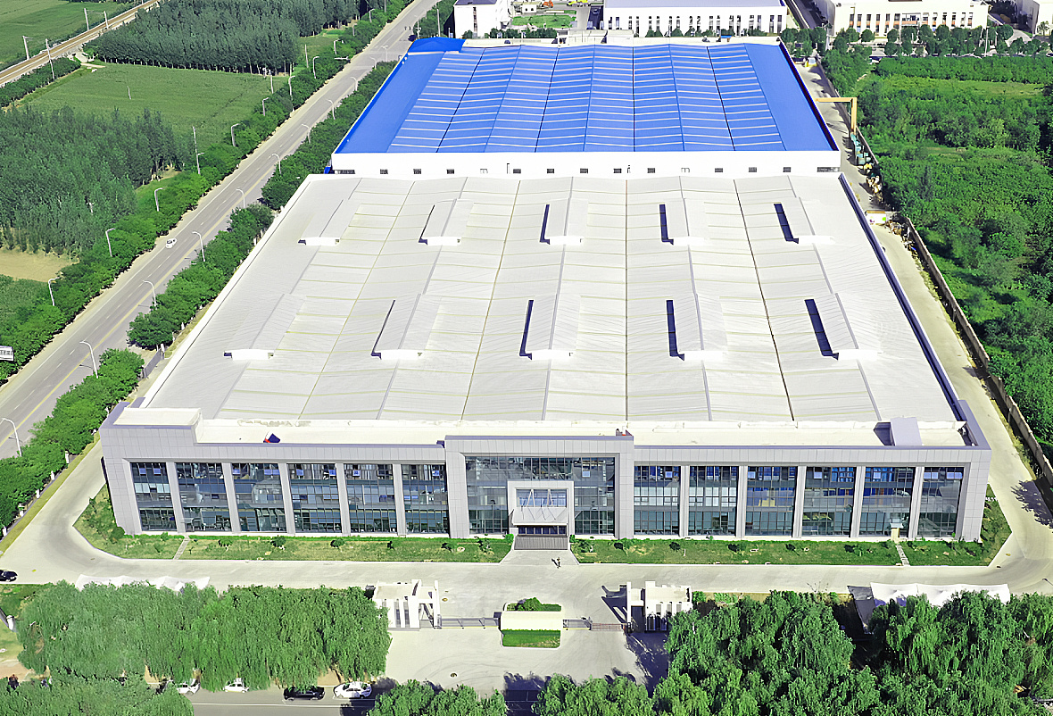
Strength Factory
years of professional production source factory

Support customization
Customize drawings and samples on demand
Testing equipment
FAQ
We have collected some frequently asked questions to help you better understand our company, our capabilities, our products and services.
Can I have my own custom product?
Yes. oem and odm can be provided, including design, logo, packaging, etc.
What is the minimum order quantity?
It depends on the product.
What are the terms of payment?
Wire transfer or letter of credit, Western Union, Alipay, etc.
When is the delivery time?
Inventory orders within 7-15 days, for oem and odm orders, the specific time depends on the actual situation
Can I take samples for testing?
Yes, samples can be sent for testing before bulk ordering.
Do you have pre-shipment inspection procedures?
Yes, we always test the products before delivery.
Leave Us A Message
Recommended Products


